
| << Contents |
| PinPoint™ Probes |
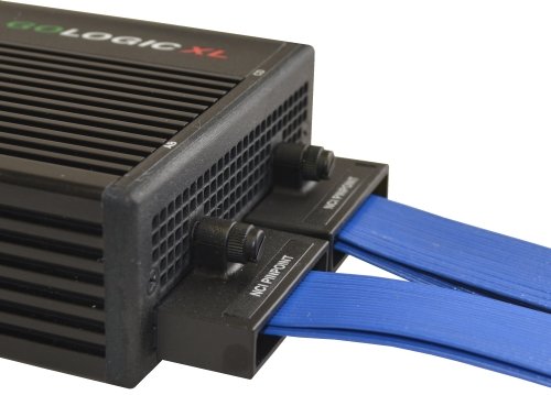
| Front Panel |
| Insert the PinPoint™ probe into the A/B and C/D connectors on the front panel. Secure each probe with the captured screw... |
|
|
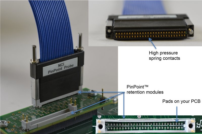
| Test Connection |
| The PinPoint™ probe connects to a PinPoint™ socket installed on your circuit board... |
|
|
| See the Appendix for a layout diagram for the pads on your test circuit. |
| The Layout diagram is also available in PDF format. |
| Copyright and trademark information |
|
|